|
1) Start by disconnecting battery so the PCM can reset.
2) Disconnect any vacuum lines and electrical wiring from the fuel rail and upper plenum.
3) Unplug IAT sensor connector at F-duct and disconnect F-duct from throttle body.
4) Unplug all three electrical connectors from the throttle body (MAF, IAC and TPS). Then remove wiring harness from passenger side motor mount bracket.
5) Do not disconnect the fuel lines! There are four 10-mm. nuts that hold the fuel rail down. You will need to disconnect these. You will also need to disconnect the electrical connectors from each of the six fuel injectors. Do not remove the injectors from the fuel rail. Once the fuel rail is loose, you will be able to move the entire assembly to the side without spilling any fuel. Be very careful doing this, especially on the older cars because the plastic fuel lines can be very brittle. Check to make sure the o-rings are still on the fuel injectors as they will help seal in the lower intake manifold.
6) Do not remove the throttle body. It will stay attached to the upper intake and shorten reinstallation time.
7) To remove the intake plenum you will need to remove ten bolts: eight 8-mm. and two 10-mm.
8) Next remove the EGR heat shield bracket and disconnect fuel lines from this bracket. Remove the large vacuum line from the rear of the upper intake plenum to the brake booster. Do this by using a slotted screwdriver to release the clips one side at a time.
9) Next you will need to remove an 8-mm. bolt from the bracket which supports the throttle body and is connected to the lower intake manifold by the exhaust crossover. You can rotate this bracket towards the front of your car to have better clearance when it is time to take out the upper intake and throttle body.
10) Disconnect the throttle and cruise control cables from the throttle body and set them aside.
11) You can now lift off the upper intake and throttle body assembly. After this step, remove the bracket that connected the throttle body and the lower intake manifold as the insert will increase the height of the throttle body and you will no longer be able to use it.
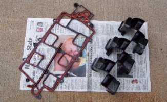
12) Turn over the upper intake manifold and remove the plastic gasket/MAP sensor tube and plastic intake runners that are clipped into the phenolic intake as shown in the image below. These will not be reused.
13) Thoroughly clean the mating surfaces of the upper and lower intake with aerosol brake/parts cleaner so there will be no dirt or oil on the surface and the assembly adhesive will seal correctly.
14) Clean the exposed tips of each fuel injector and each o-ring. Lubricate each o-ring with light grease to ensure they don’t tear during reassembly.
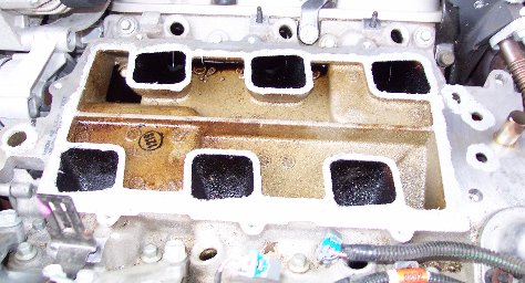
15) On the lower intake manifold, apply a ¼” CONTINUOUS bead of assembly adhesive around the perimeter of each of the six intake ports, the entire sealing perimeter and around the other four smaller holes as shown in the image below. It may be easier to use the orange sealing rings on the original factory gasket as your guideline. Be sure to take your time when applying the sealant as vacuum leaks and coolant leaks are very possible if a proper bead does not exist. Within ten minutes, place the high velocity intake insert onto the lower manifold using two bolts in the smaller holes on the right and left of the insert to center the piece. If this step is not done within ten minutes, the assembly adhesive will not set up properly, and you’ll need to clean everything off and begin again.
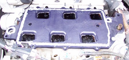
16) On the intake insert, apply a ¼” CONTINUOUS bead of assembly adhesive around the perimeter of the insert (on the lower flat surface) and around the two small holes as shown in the image below. Again take your time to ensure proper sealing of adhesive.
17) Now you are ready to reinstall the upper plenum and throttle body. You should bolt down the whole upper intake assembly as soon as possible as adhesive will dry quickly in open air thus creating possible leaks and improper seal. If this step is not done within ten minutes of applying the adhesive, it will not set up properly, and you’ll need to clean everything off and begin again. Torque all ten bolts to 89 INCH-pounds (NOT foot-pounds). Using a criss-cross pattern starting in the middle and working outwards. This step will need to be repeated a few times to make sure the seal is good. Give another 15-20 minutes of drying time and retorque the bolts again.
18) Let the assembly adhesive dry for four to twelve more hours before continuing.
19) Retorque all ten bolts to 89 INCH-pounds (NOT foot-pounds) one final time.
20) Now it is only a matter of reconnecting everything in the reverse order above and reconnecting your battery.
21) Enjoy!
Disclaimer:
Engine components fail
– especially in cars modified for increased power outputs. Engine failures
occur in completely stock engines and ones with modifications too. Your
purchase and/or installation of this product constitutes your acceptance
of any and all liability with regard to this product. INTENSE Enterprises,
Inc. and ZZPerformance will not be held liable for any engine or other
damage that occurs due to the installation, misinstallation or use of this
product.
|